The Carbolite HTF laboratory chamber furnace range is engineered for precision and performance, offering temperatures up to 1800°C.
These furnaces are ideal for a variety of processes including sintering, annealing, calcination, and other thermal treatments. Each unit in the HTF range is built with high-quality materials and incorporates advanced thermal technology to ensure uniform heat distribution, optimal temperature control, and long-lasting performance.
£48,975.00 exc. VAT
Carbolite’s HTF furnace range is at the pinnacle of furnace design. The culmination of over 80 years of experience in thermal engineering; combining the latest technological developments with solid construction and high-quality components.
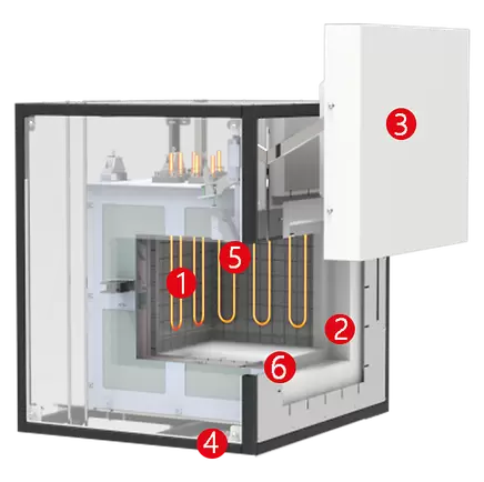
View inside the 1700 °C and 1800 °C HTF chamber furnace:
1. Heating elements (MoSi2)
2.Сeramic fibre insulation
3. Front door
4. Supporting frame
5. Thermocouple
6. Usable space
MoSi2U-shaped heating elements are installed in a vertical, hanging position within the HTF. The heat is insulated using ceramic fiber boards, layered with an appropriate thickness to enhance temperature uniformity. The maximum temperature of these boards is chosen based on the furnace’s maximum temperature requirements. Water cooling is unnecessary due to the low thermal conductivity of the insulation material. The system is externally cooled by ambient air convection within the outer case.
MoSi2 heating elements are ideal for high-temperature processes, as they naturally form a protective oxide layer at elevated temperatures. The HTF chamber furnace is distinguished by its exceptional temperature uniformity and compact design.
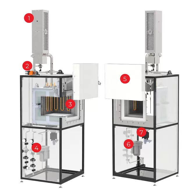
The HTF high temperature furnace range comprises 1700 °C and 1800 °C models.
The four smaller models are bench mounted and the larger units are floor-standing. These furnaces may be customised in order to satisfy specific customer requirements, e. g. the addition of debinding options for ceramic binder burn-off applications.
Carbolite HTF furnaces may be equipped with debinding and sintering options to accommodate a range of technical ceramic applications A thermally induced decomposition and evaporation of the binder occurs due to gas flow through the HTF furnace during the debinding phase. The gas flow guides vapours to leave the sample.
The sintering of oxide ceramics in an HTF 1700°C or 1800°C furnace is a critical process in materials engineering, essential for achieving optimal mechanical and structural properties in ceramic components. This high-temperature sintering, particularly relevant for materials like alumina and zirconia, optimizes microstructural characteristics, enhancing performance in demanding applications.
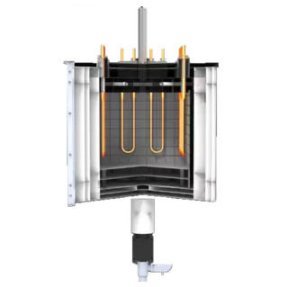
High quality MoSi2 heating elements and preheated air inlet.
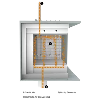
Optimised pre-heated air flow for efficient binder removal.
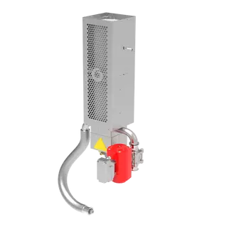
For safe combustion of binder gases an active propane gas afterburner can be provided.
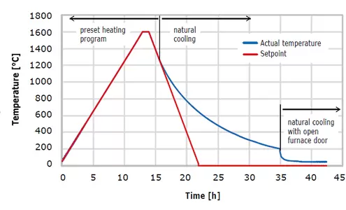
Disclaimer: The information presented shows typical performance. Furnace load ~ 8kg.
Loading: The ceramic is placed on a sintering tray in the HTF furnace, using a tray that withstands high temperatures without reacting with the ceramic.
Ramp-Up: The furnace’s temperature is methodically increased to 1800°C, with a controlled profile to prevent thermal shock and ensure even heating, possibly pausing at certain temperatures for stress relief.
Soak: At 1800°C, the ceramic undergoes a critical soak, allowing particles to merge through diffusion, enhancing density and growth.
Cool Down: Following the soak, the furnace cools to room temperature at a rate that prevents thermal stress, avoiding cracks or deformation in the ceramic.
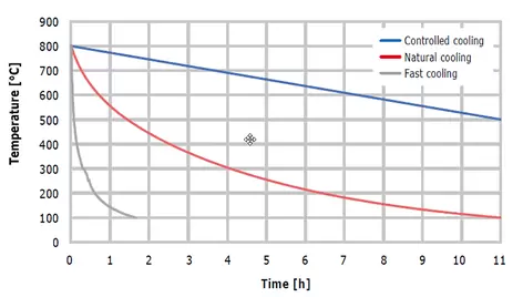
The cool down phase in sintering oxide ceramics, is crucial for maintaining structural integrity and achieving desired properties. By utilising the HTF furnace’s pre-heated air inlet blower options the user gains flexibility for their sintering processes. This feature allows precise control of cooling from sintering temperatures (1700 or 1800°C) to room temperature, preventing thermal gradients and associated stresses that could damage the ceramic.
For complex shapes or materials prone to thermal shock, step cooling can be used. With the HTF furnace step cooling can be optimised to minimize thermal stress risks by holding at intermediate temperatures to equalize internal and external temperatures. The HTF furnace can be used to tailor the cool down to each ceramic’s needs ensures high-quality components with optimal properties.
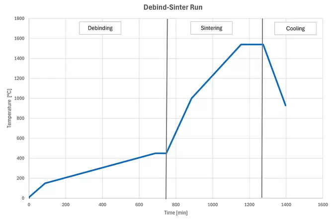
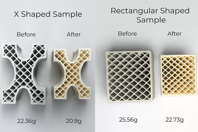
During the heat treatment process, the 3D-printed components were treated in the same furnace. The X-shaped sample experienced a weight loss of approximately 6.5%, while the rectangular-shaped sample showed a weight loss of about 11.1%.
The HTF furnaces ensures exceptional temperature uniformity with its advanced design, high-quality elements, and superior thermal insulation for minimal heat loss and even heat distribution.
Advantages of investing in a Carbolite furnace:
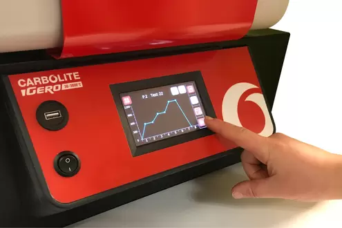
HTF furnaces are equipped with ethernet communications and a programmable controller with 24 segments as standard: :
| Max temp (°C) | Heat-up time (mins) | Dimensions: Internal H x W x D (mm) | Dimensions: External H x W x D (mm) H (door open) | Configuration | Volume (litres) | Max power (W) | Digital Ethernet Comms | Thermocouple type | Weight (kg) | |
|---|---|---|---|---|---|---|---|---|---|---|
| HTF 17/5 | 1700 | 50 | 158 x 150 x 225 | 565 x 830 x 650 (850) | Bench-top | 5 | 4050 | Standard | B | 109 |
| HTF 17/10 | 1700 | 44 | 232 x 200 x 225 | 565 x 830 x 650 (850) | Bench-top | 10 | 5920 | Standard | B | 133 |
| HTF 18/4 | 1800 | 65 | 140 x 140 x 190 | 565 x 830 x 650 (850) | Bench-top | 4 | 4650 | Standard | Pt20%Rh/Pt40%Rh | 115 |
| HTF 18/8 | 1800 | 56 | 210 x 190 x 190 | 565 x 830 x 650 (850) | Bench-top | 8 | 6200 | Standard | Pt20%Rh/Pt40%Rh | 128 |
| HTF 17/27 | 1700 | — | 300 x 300 x 300 | 1835 x 900x 1000 (1950) | Floor standing | 27 | 10000 | Standard | B | 355 |
| HTF 17/64 | 1700 | — | 400 x 400 x 400 | 2530 x 1150 x 1490 | Floor standing | 64 | 16000 | Standard | B | 555 |
| HTF 18/27 | 1800 | — | 300 x 300 x 300 | 1835 x 900x 1000 (1950) | Floor standing | 27 | 10000 | Standard | B | 355 |
| HTF 18/64 | 1800 | — | 400 x 400 x 400 | 2530 x 1150 x 1490 | Floor standing | 64 | 16000 | Standard | B | 555 |
| HTF _/128 | 1700,1800 | — | 400 x 400 x 800 | 2000 x 1000 x 1500 | Floor standing | 128 | 40000 | Standard | B | — |
| HTF _/165 | 1700,1800 | — | 550 x 550 x 550 | 2450 x 1400 x 1400 (door open) | Floor standing | 165 | 40000 | Standard | B | — |
– Heat up rate is measured to 100°C below max, using an empty chamber
– Holding power is measured at continuous operating temperature
– Maximum power and heat up times based on a 240V supply
– The uniform volume is smaller than the total chamber volume
* Dimensions of control box
Content may be subject to modifications or corrections
| Chamber Furnace Capacity | |
|---|---|
| Chamber Furnace Temperature | 1700°C |
| Chamber Furnace Main Application | High Temperature Requirements |



Fill in the form and our team of experts will recommend the best viscometer and setup based on your requirements.